Tuesday, 10 November 2020

Pi 400 My Thoughts


I mean I'm already set up to invoice Raspberry pi as a freelancer so I don't know why they don't hire me to model all the new products.. :) Yes, I have a Pi400 and in case you have been under a rock it's the latest raspberry pi offering where they have shoehorned an adapted version of the PI4 4GB into a keyboard and made a complete computer package out of the box. 

I've had mine for a few days and had time to have a little play. I'm late to the game so there are lots of reviews and tear downs out there so this is just my little collection of thoughts and findings. 

First of all, I went for the Pi400 package only, not the option with a mouse and SD card as I have those in abundance, similarly so with a micro HDMI adaptors. For setup I've used the full Rasbian image with the optional software. 

Hardware wise it feels very nice in hand. It's pretty solid feeling and is very compact. Definitely suitable to chuck in a bag and carry about and I wonder if we'll see people incorporating it into cyber deck type builds. The keyboard is a nice size and the travel on the keys is pleasant and its pretty nice to type on. I LOVE that there is a power key on F10! It's great to be able to shutdown and then, whenever you want, press the raspberry key and long press F10 to boot! So pleasant after much plugging and unplugging of pi over the years. 

There's been a lot of discussion about the fact that raspberry pi kept the micro HDMI connectors similar to the ones on the Pi4. There are a fair few people who don't approve and wondered why in this build they didn't opt for full size ones. Essentially rpi design crew reckon that micro HDMI is the most future proof and will have the longest support. I am less concerned about the micro HDMI as I've found them pretty robust in use. The one thing I wish they had done is to space them out from each other. If you use the chunky none cable type micro HDMI to full size adaptor it's impossible to use two of these side by side in the micro HDMI sockets. So a little tip is to go for the cable style adaptors. 


In use, it's pretty capable. The slightly updated processor IC has been overclocked to 1.8 GHz but theres a heap of thermal gubbins inside so its totally cool and stable. It zips along quite readily and runs the usual games and programming stuff bundled in the raspbian image. I've also tinkered with inkscape and KiCAD on it and it handles these really well. Similarly web browsing and video streaming all works fine. For general office, light browsing and stuff there is very little it can't do. 


One other thing I was interested in was that the custom board featured a different WiFi antenna with a PCB routed antenna rather than the PI4 antenna. Whilst I've stopped short of measuring gain etc I definitely have noticed that I get a better connection to my WiFi from my lair! 

Final thoughts are, I think it's great. It's brilliant for me in that often I have to try odd things on a RPI for work/writing and I've wanted a more permanent set up for a while. I like that it can be chucked into a bag for trips. I think that if you have someone curious to get into programming or tinkering with project this is an excellent out of the box accessible setup for not much coin. I'm planning to tinker with getting it up and running as a controller for my CNC router and perhaps my Vinyl Cutter as well as a general tinkering machine, 


Thursday, 5 November 2020

Boat building in Hackspace magazine 36!


So most months I update this post with a brief line describing what articles I have in the current issue of Hackspace magazine, but occasionally they warrant a post all of their own! In this months issue 36 I am really pleased to have been featured in this article about my adventures building a plywood boat. "Cysgod" the boat has been a brilliant project and as ever I learn't loads and had fun with the bonus great feeling of eventually getting to travel local lakes in a craft I built! 

One photo I submitted didn't quite make the editorial cut, but I love this photo of "Cysgod" having been commandeered by Seren, who has a decent claim on this boat having helped out on the build and also, if I am honest, it probably fits her better! 


Sunday, 18 October 2020

Laser Cut Hinges


I've been making this little plinth/stand that's going to have my Super Adept Lathe mounted on it for a while and last week I took the front of the plinth to the Ffiws makerspace and laser cut the two holes. The idea originally was that it would just be a little cubby hole to store odd bits and bobs. However the kerf is so fine with the laser that I couldn't help but think it might be nice to keep the cutouts as doors. So it got me thinking about hinges! I'd seen this method ages ago on something at a maker event but had never tried the principle. 

Above you can see the component parts, all cut from 3.125mm ply the 6mm diameter hole and plug already have a nice clearance due to the laser cut. The idea is that you carefully glue the little circular plug to the solid pieces taking care not to het any glue in the mechanism.
The idea is contingent on making the holed section/arm slightly thinner than the plug, so some nice even sanding (around 12 strokes per side) gives enough clearance for the hinge to be solid enough yet still move. 


Finally gluing the final solid piece to the hinge, and again you have to take care to not get any glue into the rotating section. I think an improvement would be to create some kind of jig so that you  can set these up with longer drying wood glues which would make them stronger, but they seem ok for now with super glue. 


Glued up the cubby door side before affixing them to the main assembly. 

Sunday, 4 October 2020

Casting Silicon Tyres.


I'm definitely into developing robot stuff at the moment and after the MTV robot project, where I built everything apart from the chassis, I wanted to build some chassis ideas for a smaller platform. The first attempt is above, a CNC'd folded aluminium chassis with 3d printed wheels on which are riding DIY glow in the dark silicon tyres!

I wanted to share my process, the first thing to know is that I've used some really cheap silicon, the type of silicon used in bathrooms as seen above. The important thing is that it is pure silicon with the acetic acid smell as it cures. If you open the tube and it smells very vinegary you have the right stuff!

I've been using about this much silicon per batch, it's about a golf ball size blob and is plenty for a set of 4 small tyres. To it I am adding a pea size amount of acrylic paint, and I happened in these first batches to use some glow in the dark acrylic paint. It doesn't seem (even with different colours) to matter if you put more in than a pea size amount as the tiniest blob seems to colour the silicon well. I'm also adding a few drops of glycerin, the glycerin seems to thin the silicon slightly but certainly seems to make it flow a little easier.
I simply CAD'd some moulds, they are in 2 parts and the small pip and hole correspond to ensure that the mould and the core are centralised creating an even tyre. In the photo above you can see that I've packed the mould with some of the mixed silicon before squeezing the mould core in. 


Squeezing the two parts together you get a lot of material pushed out of the sides, which you can scrape off and put into the next mould. Make sure that the moulds are fully closed so the walls of the tyre stay nice and vertical. 

Above you can see the filled moulds, I left the first set for around 12 hours before turning them out but later sets have been happily de-moulded after around 3 hours. At 3 hours the tyres are strong enough to be removed and handled but still smelt quite strongly indicating that they aren't fully cured. 

Pulling out the mould core they seperate cleanly and the tyres are nicely formed. Having made about 12 of these now I haven't had any with any air bubbles or defects. They need a little cleaning as they tend to have a little "flash" silicon around the edges but it's easily removed. The tyres are strong yet very soft and grippy. I'm planning to experiment with fitted tyres and also treaded tyres in the future but for now these tyres fix to wheels very well using a thin film of super glue. They glow nicely as well! :) 

Wednesday, 30 September 2020

Lil' Lights, Adventures in PCB's, FLIR and high power LED's


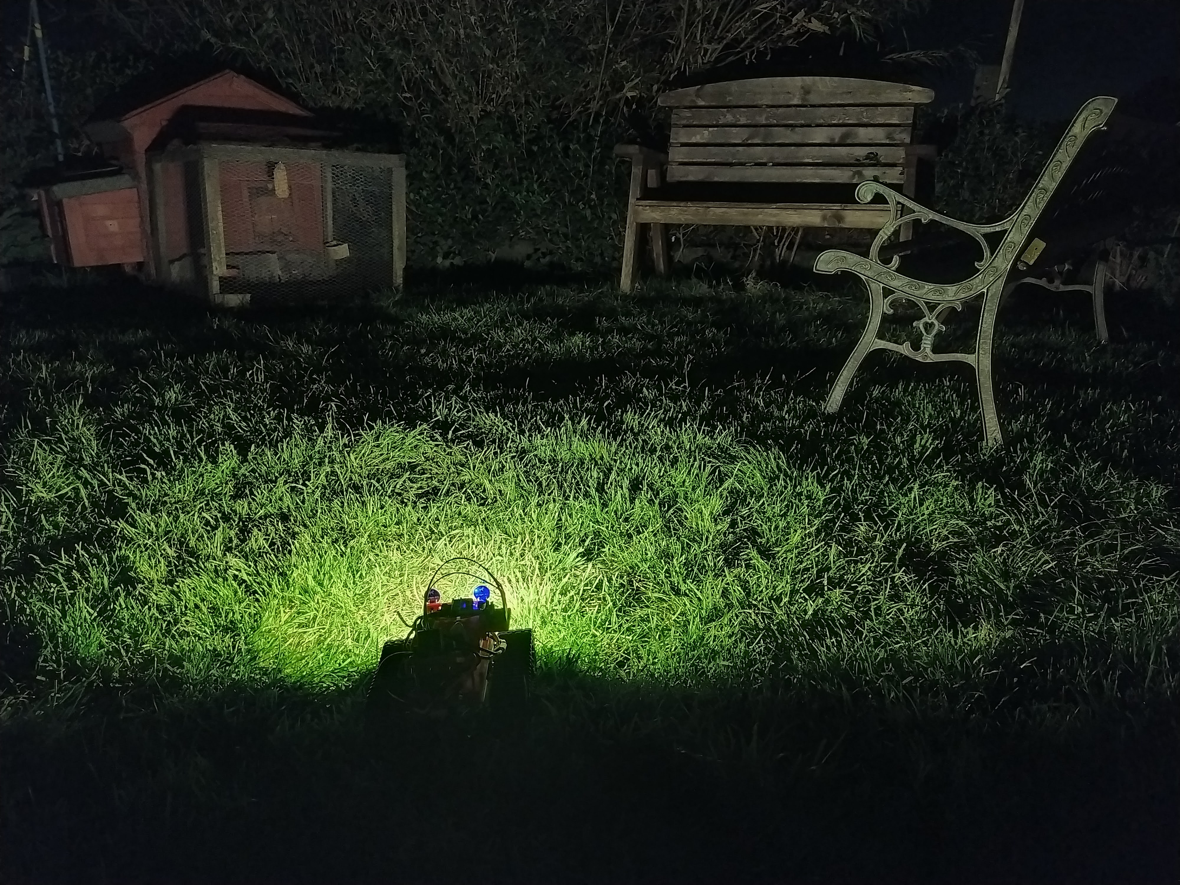
After designing the MTV robot I've been slowly tinkering with numerous add ons. I wanted to add some high power LED lights and so I bought some 1 watt white LED's in an SMD package. They offered a lot of light and I'd read that the 1 watt LED didn't need heatsinks to keep the running temperature within the datasheet operational temperature range. 

Testing them on the bench they get hot enough to be uncomfortable on the fingers so I decided that a PCB breakout that enabled them to be easily mounted but also acted as a slight heatsink was desirable. I quickly whipped up a design using the fabulous inkscape plugin SVG2Shenzhen and finished the design off in KiCAD . The PCB has a large pad that interfaces with the LED "slug" and in the PCB pad there are some via's connecting that pad to the large copper flood on the back of the PCB. This flood is under the mask so heat doesn't dissipate massively but I wanted it to just slightly reduce the temperature of the LED. When soldering on the LED I've added a small spot of thermal grease between the LED slug and the PCB pad. Finally I made sure that the M3 mount hole (3.2mm diameter for clearance) wasn't copper plated so that hopefully the heat in the LED and PCB wouldn't wick into mounting bolts etc. 

I got some of the PCB made by the fantastic OSHpark  and mounted up some LED. Driving them at 1 watt is made simpler by using one of the cheap constant current capable DC-DC buck driver boards that are readily available now. They certainly are bright! 

I wanted to test how well everything was working and a friend kindly lent me his very nice FLIR camera. You can see a couple of things below comparing images from both mounted and unmounted LED's, firstly the PCB does indeed reduce the overall temperature a little as compared to the unmounted LED. Rather splendidly you can also see that the PCB mount hole doesn't couple and transfer the heat which is nice to know when bolting them into 3d printed parts. 


Above left is the front of an unmounted 1 watt LED. Above Right is the front of an LED mounted on the PCB


Above left is the unmounted LED rear and above right is the rear of the PCB with mounted LED.


Above is a FLIR image of an M3 bolt placed through the mount hole of a PCB mounted LED. 

Get in touch if you are interested in getting any of these boards as I might put some on a tindie shop at some point. 


Monday, 14 September 2020

Unboxing and quick review of the Valenta Off Roader robot kit.


Quick video unboxing and assembling a Valenta Off ROader robot I won in a twitter competition!

Tuesday, 8 September 2020

Budget Eyewear Options for Close Up Work!


I'm comfortably slipping into that age range where eye strain is easily found and when the "ready reader" glasses are not too far away at any given time. Although I have always used lenses and loupes for close up work I am wearing them more often for a an increased variety of tasks. I've been quite happy with my choices until recently when wearing ones with a traditional nose arms and pads have started to annoy my nose and cause a bit of soreness, probably due to wearing them and glasses more often! So in a fit of random old maker blogging I though I'd do a round up of my crop of cheap close up work systems!

First up above (and modelled below) are my oldest pair which are essentially a set of loupes on a wire frame with some LEDS. The LED's on this type are rubbish using none rechargeable little coin cells with fiddly little switches and inside pretty poor quality plastic cases that promise to be move-able into any position but rarely stay where you want them to be! The loupes themselves are pretty good and powerful but only put stuff in a working range/focus about 15mm away from them. Far to close for soldering etc but actually can be very useful for looking at tiny mechanisms or indeed for hunting solder bridges or inspecting small joint on PCB's. The loupes can be rotated away from the eye and so you can flip them on of off without removing the frame. They aren't that heavy so can be worn for long periods. 


Next up, below, is these white plastic frames with interchangeable lenses, mine came with a set of 5 lenses promising a range of magnification from 1.5 x through to 4x. The lenses themselves are in a separate box and snap into place and can be rotated which is nice in that you can adjust their position relative to your eye. I find the 1.5x magnification can still return me a working distance of around 20-25cm which I find quite nice in terms of SMD soldering and other small work. They have 2 white LED's mounted above the lens and you can tilt the LED mount down and up to change the angle of them which works well. These take 3 AAA batteries and they are mounted in the front of the frame. I've found these brilliant for a long time but noticed that the combination of a standard glasses type frame that balances over your ear and the batteries at the front makes them feel front heavy and that they might slip off. They never have to be honest but these are the ones that of late, due to increased usage and reliance on them have started making my nose a bit sore! I've found these available online for between £9 and £15.


As previously it seems only fair to let the resident supermodel show off how hot these make you look. :)


So finally we come to the new kids in town! Pictured below these are similar to the last pair but I wanted to try a set that had a headband arrangement rather than a spectacle type set up. This set have a nice around 40mm wide padded and adjustable headband which can be set up to suit the wearer. They offer lots of support and the whole of the white assembly can be rotated up and down without removing the headband. They have a set of lenses similar to the previous set (in fact they are interchangeable) but the 1.5x lens is permanently attached in the frame and you can add more lenses behind if needed. They also have this pop down loupe which I haven't really found use for as yet but it amuses me in how brilliantly dorkish it looks! This set have 3 LEDS and they are powered by 3 AA batteries. You can tilt and adjust the LED up and down and side to side and you can also remove the LED and batteries out of the headband as a complete unit. If you don't want this extra weight on the front and don't need the lighting this is a nice feature! The LED's in this set also have 2 power settings which I guess offers more flexibility. I've found this set online between £12 and £25 so shopping around is definitely worth it. 
This final set have totally got rid of the nose irritation the previous set started to give and they also feel way more secure on your head and are pretty comfortable for a long close up session... Again.. I leave it to readers discretion to work out how "cool" they might make you look!