Monday, 28 October 2024

DIY Opensource Land Navigation Tools.


I’ve been practising my land navigating a little bit recently. With the short days and winter weather it’s useful to practice walking on bearings and other navigation techniques for when visibility suddenly worsens! As part of this I've made some DIY navigation aids. First up is some DIY lasercut perspex roamers. This was partly as I wanted to write an upcoming tutorial on the Inkscape Ruler Path effect (See recent other posts on the offset path effect and the corners path effect) which allows you to create precise graduated ruled scales perfect for all kind of measuring tools.

A “roamer”, or “romer” as some people spell it, is a tool that’s particularly useful when it comes to defining a grid reference on a map. The premise is pretty straight forward you identify the first two numbers of the grid reference directly from the line labels on your map and you then place the zero corner of the roamer on the position you want to create a grid reference for and then read where the roamer scale crosses the map lines to the left of and below the zero point. As an example in the image the grid reference of the Pumping Station marked on the map could be given as SH605641 or even more accurately estimated as SH60556413.


Many compasses have roamers marked on them for common map scales but this project started as my older Silva compass I’ve had for years didn’t have a roamer for 1:40000 scale which is the standard map scale for Harvey maps. After drawing the scales in Inkscape I then added a couple of scaled holes in the roamers which are handy for defining a circular area of a known radius on a map.

I’ve posted the roamer designs as they stand here and they are perfect for laser cutting and engraving, but equally, you could print them on card and they would work just as well!

Secondly I’ve been making some “ranger beads” from Paracord which is an interesting pretty knot with which you can create a sliding bead. A great use for these is they can replace a cinch toggle which is handy but you can also use them to make a great set of pace beads for navigation. There are many tutorials for this knot online like this video on Youtube.

The premise of pace beads is to keep track of the distance travelled on foot and it’s super handy if you suddenly end up walking on a compass bearing with no visibility. I’ve tied 10 ranger beads onto a doubled length of Paracord and then I can slide one bead to the opposite end of the cord when I have travelled 100 meters. To identify the 100 meters you need to somehow mark out 100 meters on a flat surface and then walk the distance counting your paces. It’s common to count 2 steps as a pace so for example you count every time your left foot lands. A good place to find 100 meters marked out is an athletics track on a local sports field, but failing that you can use online maps to drop a pin at a location and then measure out from the pin 100 meters and note exactly where that is. I’m quite tall so my average paces for 100 meters is 58 paces. I loop the pacer beads onto my rucksack strap and then as each 58 paces passes I pull a bead to the bottom, resetting all the beads when I have done this 10 times (Note I could really have just tied 9 beads as the resetting could be the tenth!). 

It’s really accurate, with practice you can even adjust your pace number for when you travel uphill or downhill and I find that I can, checking with the Ordnance Survey map route plotting and other GPS mapping) I can keep to within 50 meters accuracy over 2km, way more than you would travel without checking on a bearing.


Friday, 11 October 2024

Inkscape Path Effect: Offset


The Offset path effect can be used to create multiple effects. One useful application that helps to explore it is to create an offset outer path around a design. An offset outer path is useful potentially for design aesthetics but also useful for applications such as using a print and cut vinyl cutter or a laser cutter where you might want to print/engrave a design and then cut around the design following it’s contours.


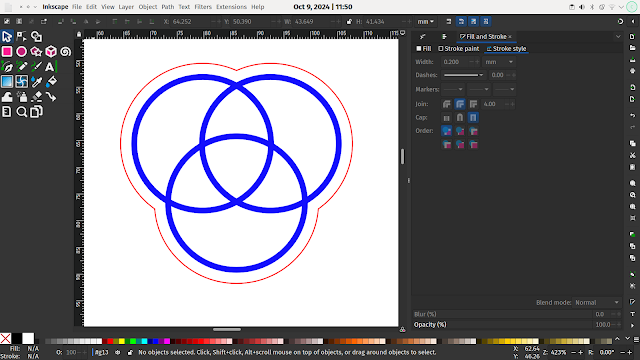
As an example lets create a small logo and then create an outer offset path. To begin left click the Ellipse/Arc tool icon and then on the canvas left click and hold, whilst holding the control key, drag to the right to create a small circle. With the circle selected click “Object – Fill and Stroke” to open the fill and stroke dialogue tab on the right hand side. Selecting the “Fill” tab click the “X” icon to turn off the circles fill. Selecting the “Stroke Paint” and then “Stroke Style” tabs set the stroke width and colour so it looks similar to our image.


With the circle selected press control and C and then control and D to copy and paste a copy on top of the original then move the copy to the side. Create one more circle copy so you have 3 identical circles. Position the circles so they are similar to the overlapping design in the image. You can use the Align and Distribute tool tab found under “Object – Align and distribute…” to achieve this, or for this simple example, just align them by hand.


Next press control and A to select all three circles. Next click “Path – Stroke to Path”. This operation converts the circles strokes which currently sit on a central path in each circle so that there is a path at either side of the stroke. To be able to see this you can click “View – Display Mode – Outline” this display mode is useful as it shows paths as outlines with no fill detail visible. You should see each circle now has an inner and an outer path. Finally with the three circles still selected click “Path – Union” and you should see that your design is now one single object and the paths do not cross similar to the image.

Quicktip: Making a union of paths is incredibly useful when using tools like vinyl cutters where we don’t want paths to be cut in overlapping sections of a design.


Moving back into normal display mode by clicking “View – Display Mode – Normalwe can now use the path effect to create a path around the outside of our design. To begin this select our circles logo and then press control C and control D to create a copy. To make it easier to see what is happening let’s move our copy away from the original but leave it selected. Next press “Path – Path Effects” to open the Path effects tab in the right hand panel. From the path effects dropdown click Offset. In the resulting dialogue check that the unit is set to “mm” and enter a value, we added 2 mm. You should see that every path in the selected set of circles is now offset from its original position by 2mm as in the image. Changing back into the “outline” display view if you select the item using the “Node Tool” you will see that the nodes of the path are still in the original position of the circles. We next want to edit the Offset design so to do this we are going to click “Path – Object to Path” the offset design should now be paths rather than an effect and so the nodes will be editable on the actual design as seen in the image below.


Finally we can select the “Node Tool” and then use this to select the nodes of the internal paths and delete them so that we end up with just the external path created by the offset effect.


Moving back to the Normal display mode you will see that probably your new single path object has a fill, use the fill and stroke tools to turn off the fill and set the stroke size and colour to make a thin visible line. Next you can use the Align and Distribute tools to re align the new offset path around your original 3 circles as seen in the header image.


Tuesday, 8 October 2024

Inkscape Path Effect: Corner


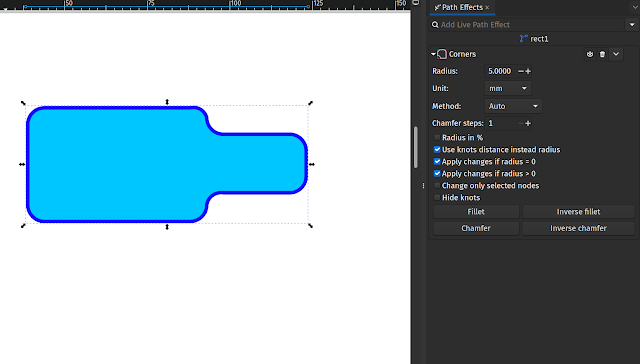
The Corner path effect can be added to reasonably complex paths to create radius corners. It’s a relatively straightforward path effect to use. As an example lets create a shape with a pair of rectangles and then apply the Corner path effect. 


To begin click the Rectangle Tool icon and then left click and hold on the canvas to start drawing a rectangle, drag the tool across the canvas to create a rectangle. Create a second rectangle and roughly arrange them as seen in the image.


Quicktip: If we just want to add rounded corners to a single rectangle or square we can select the item with the Node Tool and then either drag a circular node or type a radius into the Rx or Ry dialogue boxes.


Next press “Control A” to select both rectangles and then Path – Union to make a single object from the two rectangles as shown in the image.


To add the Corner path effect first select the union shape we just created and then click Path – Path Effects to open the Path Effects tab on the right hand side of the screen. You should see in the tab that the object, named “rect1” is listed below a search input box which has a dropdown menu. Left click on the arrow at the right side of the input box and you should see the available path effects as shown in the image.


Left click to select the Corners path effect and you should see the dialogue with the parameters for the corners path effect in the right hand tab. As a simple example of applying a corner effect let’s set the Units selection to “mm” and then type “5” into the Radius input box.


You should now see that the corner path effect is added to both the internal and external corners of our shape, you can see this in the header image at the top of this post. To remove the corner path effect at any time you can click the dustbin logo in the corners path effects dialogue.