Tuesday, 22 May 2018

New DIY Rocket Fin Jig

 So wanted to make a more accurate and adaptable system for ensuring rocket fins go onto builds accurately and I've (after a few iterations) come up with this design. It uses some established ideas floating around the rocketry community that pertain to guillotine style jigs but I've made mine to be a little different in that it is baseless and doesn't need to be placed on a board. Also the lower support for the rocket body tube is adjustable to hold a range of diameters. As such this jig can accommodate a range from the smallest Estes bt5 tube at 13mm diameter to a maximum of 80mm. Hopefully the rest of this post explains a little bit about how I made it, why and how it is used.


The three plywood plates I designed in Inkscape and cut on my CNC router. The reason I went for a threaded bar design instead of a base is that the central plate can be moved within the rails and can therefore be used for very short rocket air frames or can be made to hold the body tube securely whilst avoiding a body tube anomaly such as a camera housing etc. Using threaded bars also gave me maximum adjust-ability and meant that I could assemble the jig with utmost care for parallelism and making everything square.


 Looking underneath the fin holding aluminium rails the CNC'd wooden sections have the inverted V to receive a body tube. The point of the V aligns with 2 smaller V sections (seen at the top of this picture just beneath the aluminium angle rails.) this means a fin inserted into the small V is aligned with the centre of the body tube. You can also see in the above picture that there are some small holes and a shock cord passed through with some salvaged toggles to put a bit of tension on it. This shock cord can also be moved to a higher set of holes to support the range of body tubes.
 So here is a larger body tube (around 56mm OD) being held in the jig
 And above is a picture using the shorter setting and holding a smaller 24mm tube.

Above is a shot showing the adjustable rails that can slide left to right and then be tightened into position. The position is accurately set by inserting a fin into the V section to centre it and also placing a spare fin or a spare piece of fin material at the far end of the jig into a matching central V slot. Then the jig rails can be tightened and after an alignment check the fin glued. Then the tube can be rotated and realigned without resetting the jig to attach the next fin. The fin setup can be seen below with a fin and some fin stock at each end of the adjustable rails.


So there we go... hope it makes sense and feel free to ask any questions in the comments!

Monday, 7 May 2018

Imp... my UK Rocket Altitude record!


 So.. Had a fab weekend. I travelled down to the mighty BigEARS rocketry event (another post on that later) and whilst I was there I finally got to launch my imp scratch built rocket and set a new UK rocketry altitude record in the A impulse class! The previous record was from 2013 and set at 143 metres and I am very happy to report and show that imp achieved 214 metres!

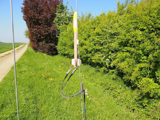
So above is imp just prior to launch, I managed to nearly half the mass of this rocket  compared to the previous record holders airframe. Imp weighed just under 18grams and this was achieved through some saving of weight due to the altimeter but also through my 3d printed transition and nosecone. I printed both these objects as a single filament line wall 0.4mm wide with no infill, I then sanded the outer surfaces smooth further reducing the wall thickness... the nosecone weighed less than half a gram!

As you can see I went for a standard rod deployment with a short standoff lug and there are certainly gains to be made if I did another attempt using piston ejection launch methods. I sanded down the estes tubing to reduce weight and also did a small bit of an attempt to aerofoil the thin balsa fins.. I now have some thin 0.8mm g10 fibreglass sheet in stock and would probably go with that as a fin material if I had another attempt!


I fiddled about on the pad for far to long getting it to sit right and at the height on the rod I wanted. Then returned to the control box and got the countdown from the very experienced range safety officer (RSO) Rod Stevenson. It leapt off the pad and shot away... it wasn't actually the most straight or vertical flight so, again, some gains to be had there. It deployed its small silver mylar streamer well and came down ok. Took quite a while to find the tiny airframe but me and my brilliant teammate Seren Hinchliffe searched and recovered it with payload section and airframe intact. We walked back to the RSO area, nervously opened the payload section and retrieved the altimeter... which was happily blinking so I knew it had logged ok! (Incidentally I followed the Perfectflite guidance diligently on the vent hole advice which resulted in 4 holes at 90 degrees at 0.8mm each around the altimeter bay).

I gathered a legendary bunch of witnesses, Rod Stevenson, (EARS  RSO), Charles Simpson (UKRA Chair) and Andy Mell (UKRA council) and a few others and we counted the blinks on the altimeter indicator led numerous times making sure we all agreed and had seen it (and I video'd the LED!). It reported 703 feet which converted to a shade over 214 metres... :) Job done! Massive thanks to the above and particularly Charles for nudging me along that morning to fly and also massive thanks to my team mate.. Seren who took photo's, carried stuff and helped massively in the search part of the flight!


A happy, hot and been camping in a field scruffy record attempt team. x

Wednesday, 2 May 2018

Toolmaking - Stud Clamps


I love making little tools. I've been meaning to do this one for a while but I finally got round to it as I needed to do some work on an M4 threaded assembly. A few years ago I did an engineering operations qualification at night school and I had to make numerous different tools/jobs to finer and finer tolerances, one of the jobs was the larger stud clamp in this picture. Basically you cut and tap some hole for a range of threads (in the case of the larger one M6 to M12) and then cruelly are made to hand cut all the way through your work piece ( a test of nerve and skill on the course as it needed to conform to the specified tolerances!). The resulting object is very useful for a few different tasks... Primarily if you thread a bolt or threaded bar though a hole and then clamp it in a vice the cut section closes tightly around the threaded object and allows you to work on it/cut it etc with it held firmly and without any damage to the object. A secondary use is if you have a threaded stud stuck into something with little to grip onto to remove it (imagine a cylinder head stud for example) you can thread on the stud clamp and then clamp the cut end with a pair of mole grips and it creates a hug wrench to remove the stuck stud with.

So it tends to be that M6 is the larger end of stuff I work on and therefore I decided to make a smaller version for the sizes M2, M3, M4 and M5, I used a little piece of en1a and again did the cut with a hacksaw... which is on the limit of being too wide for the M2 section but just left enough thread to form a precise clamp! I also chucked some drill bit gauge holes into the piece for the drill sizes needed to drill a hole to tap for M2,3,4.

Its not to as high a standard as the larger one in many ways, but is functional and I do get a great sense of satisfaction out of making things like this... with a bit of care this tool should see reasonably regular use in my shop for the rest of my making days!